In order to meet the needs of major port companies in transforming the front girder of shore container cranes so that the transformed front girder can meet the operating requirements of the latest ultra-large container ships, a core device for lengthening the front girder was developed. The device is mainly composed of a fixed cantilever crane, an aerial mobile platform, a transverse mobile trolley, etc. It can realize the multi-box lengthening of the front girder in the air, and the length can reach 6 m. Through mathematical modeling and finite element analysis methods, the lengthened front girder structure was analyzed, and a plan to increase the back arch structure was proposed, which can effectively improve the structural stiffness and strength of the lengthened front girder. Taking the front girder with a forward reach of 65 m as an example, by comparing the wire rope tension and motor power before and after the extension, it is proved that the impact of extended forward reach on the pitch system is controllable. The use of the front girder lengthening core device can help more port companies complete the lengthening and transformation of the front girder, and to a certain extent shorten the construction period and reduce construction costs.
Shore container crane (hereinafter referred to as “quay crane”) is a professional equipment for loading and unloading containers loaded on ships on the shore of the port terminal. Its loading and unloading capacity and speed have a direct impact on the efficiency of port operations. In recent years, with the deepening of global economic integration and the increasing volume of cargo transportation, the size of the ultra-large container fleet is also booming. Following the 3E 18,000 TEU container ship, the 3E Plus container ship is also constantly setting new container capacity records. On December 29, 2021, the world’s largest 24,000 TEU container ship was successfully undocked, with a length of 399.9 m and a width of 61.5 m, marking a new milestone in the stacking height and width of container ships.
At present, the widely used post-Panamax quay cranes generally have a reach of 50 to 65 m. Due to the limitation of the reach, they cannot fully meet the operating requirements of the latest ultra-large container ships. The quay cranes of major port companies in the world are facing the need to update Replacement. [2] For most port enterprises, purchasing a new quay crane is a heavy burden. From the establishment of the procurement plan to the putting into operation of the new quay crane, the cycle is usually more than 2 years. At the same time, it is extremely difficult to deal with the existing quayside cranes of port enterprises, and the cost of dismantling them is very high. If the quayside cranes are left idle, they will occupy a large area of land. Therefore, after comprehensive consideration, lengthening the forward reach of the existing quay crane is the preferred solution for most port enterprises.
The traditional method of lengthening the front reach is to use large lifting equipment such as floating cranes to lift the front girder to the ground for modification. The operation is difficult and the modification period is long. In order to meet market demand, Shanghai Zhenhua Heavy Industry has developed multi-container aerial lengthening technology and its core device with independent intellectual property rights. It has been successfully applied in many domestic and foreign ports such as Guangzhou Port in China and Algeciras Port in Spain.
The quay crane structure is mainly composed of front girders, rear girders, door frames and other structures. The rear beam and door frame are static structures and their positions are fixed. The front girder is a dynamic structure, and its position can be switched between a raised state and a flat state. This design is to meet the ship-giving conditions at the dock site.
The function of the quay crane pitching system is to switch the position of the front girder. In order to prevent the lengthening of the front girder from causing damage to the pitching system of the quayside bridge, the cantilever end of the head of the front girder can be selected as the location for installing the extension section. The cantilever end of the front girder head is located above the sea surface, and the height from the shore of the pier is more than 50 m. In the traditional front girder lengthening plan, large lifting equipment such as floating cranes must be used to lift the front girder to the dock surface for modification.
The extended core device is mainly composed of a fixed cantilever crane, an aerial mobile platform, and a transverse mobile trolley. The composition of the extended core device is shown in Figure 1.
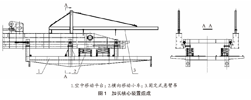
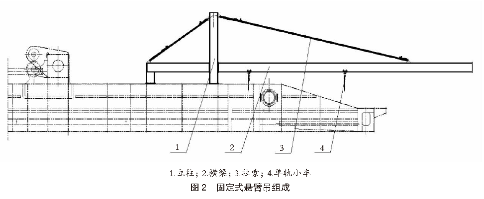
Fixed cantilever cranes are installed above the front girder, one on each side. Through the monorail trolley on the cantilever crane, the cut end front girder structure section can be translated 6 m toward the seaside.
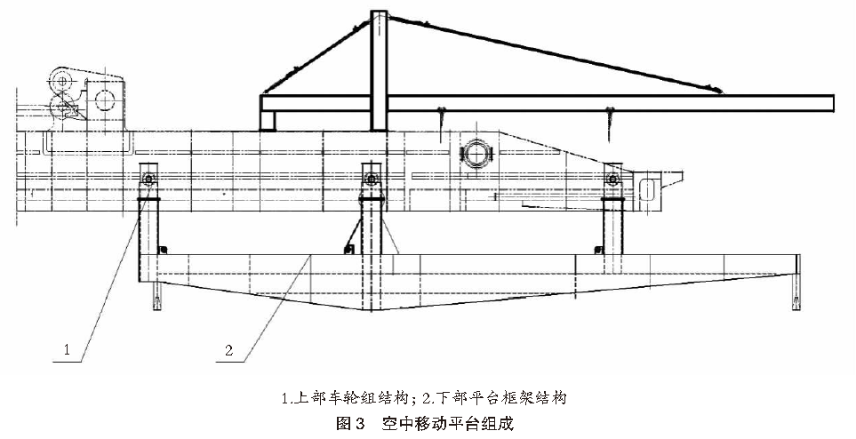
The aerial mobile platform is mainly composed of an upper wheel set structure and a lower platform frame structure. The upper wheel set structure is placed on the quayside crane trolley track. There are 3 sets of front and rear wheels, a total of 6 wheels. They are connected to the quayside crane trolley by connecting rods and can move forward and backward with the quayside crane trolley. A simple track is set up on the lower platform frame, and railings are installed around it. The platform is both a load-bearing structure and a working platform when the extension section is installed.
The horizontally moving trolley is installed on a simple track, and a hand chain hoist can be used to move left and right. Anti-sliding blocks are installed at both ends of the track to prevent the trolley from moving to the extreme position and leaving the track. Jacks and sleepers are installed on the mobile trolley, and the extended section structure is fixed above. The jack can be used to adjust the extended section in the vertical direction.
The position adjustment of the extended section structure can be completed by the cooperation of the mobile platform, transverse moving trolley and jack. Precise alignment before welding can ensure the straightness of the extended front girder.
All components of the extended core device adopt a modular design and can be loaded into containers and transported to construction sites around the world, effectively improving transshipment efficiency and reducing transportation costs.
The fixed cantilever crane mainly consists of columns, beams, cables and monorail trolleys. These components are hoisted to the quay crane trolley through the maintenance crane in the machine room, transported to the front girder, and installed on the front girder. The composition of the fixed cantilever crane is shown in Figure 2.
The aerial mobile platform is divided into an upper wheel set structure and a lower platform frame structure. The upper wheel set structure consists of 3 sets of wheels. The three sets of wheels are hoisted to the trolley track in sequence using a truck crane and arranged at designated positions according to the designed spacing. The lower platform frame structure is divided into three sections, and flange bolts are used to connect the three sections. The work of assembling the lower platform frame structure and installing the platform railings is completed on the ground. It adopts a flange bolt structure and uses a truck crane to lift the lower platform frame structure as a whole, and complete the docking and installation work between the upper and lower structures of the mobile platform in the air. The composition of the aerial mobile platform is shown in Figure 3.
A connecting rod is installed between the aerial mobile platform and the quayside crane trolley so that the platform can move forward and backward with the quayside crane trolley.
Use a truck crane to hoist the transverse mobile trolley, jacks, sleepers, telescopic craft supports, and four 3 m long extensions to the mobile platform. The mobile trolley is installed on a simple track. Jacks and sleepers are installed on the mobile trolley in sequence, and the extended structure is placed above the sleepers. All structures and tooling should be fixed to prevent the platform from slipping when it moves. See Figure 4 for the lifting position of the extended section of the front girder.
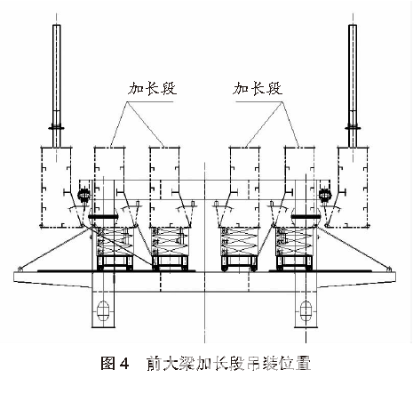
Anti-sliding blocks are welded at both ends of the simple track to prevent the mobile car from leaving the track when it reaches the extreme position. At the same time, pull ears, hand chain hoists and steel wire ropes are installed at both ends of the simple track to move the extended section structure in the left and right directions.
The monorail trolley on the cantilever crane moves to the head of the front girder and is connected and fixed with the front girder body to be cut. Use a semi-automatic flame cutting device to disconnect the front girder, and use a mobile monorail car to move the head girder forward 3.2 m, leaving room for the extension section to be installed. See Figure 5 for the installation location of the front girder extension.
The horizontally moving trolley moves the 3 m long extension structure of the first section to the designated position, and adjusts it according to the position of the rear girder. After the adjustment is in place, it is aligned and welded with the rear girder.
The mobile platform is moved forward and the second 3 m long extension structure is added. After being adjusted in place, it is aligned and welded with the first extension section and the head beam body. The installation diagram of the extended section of the front frame is shown in Figure 6.
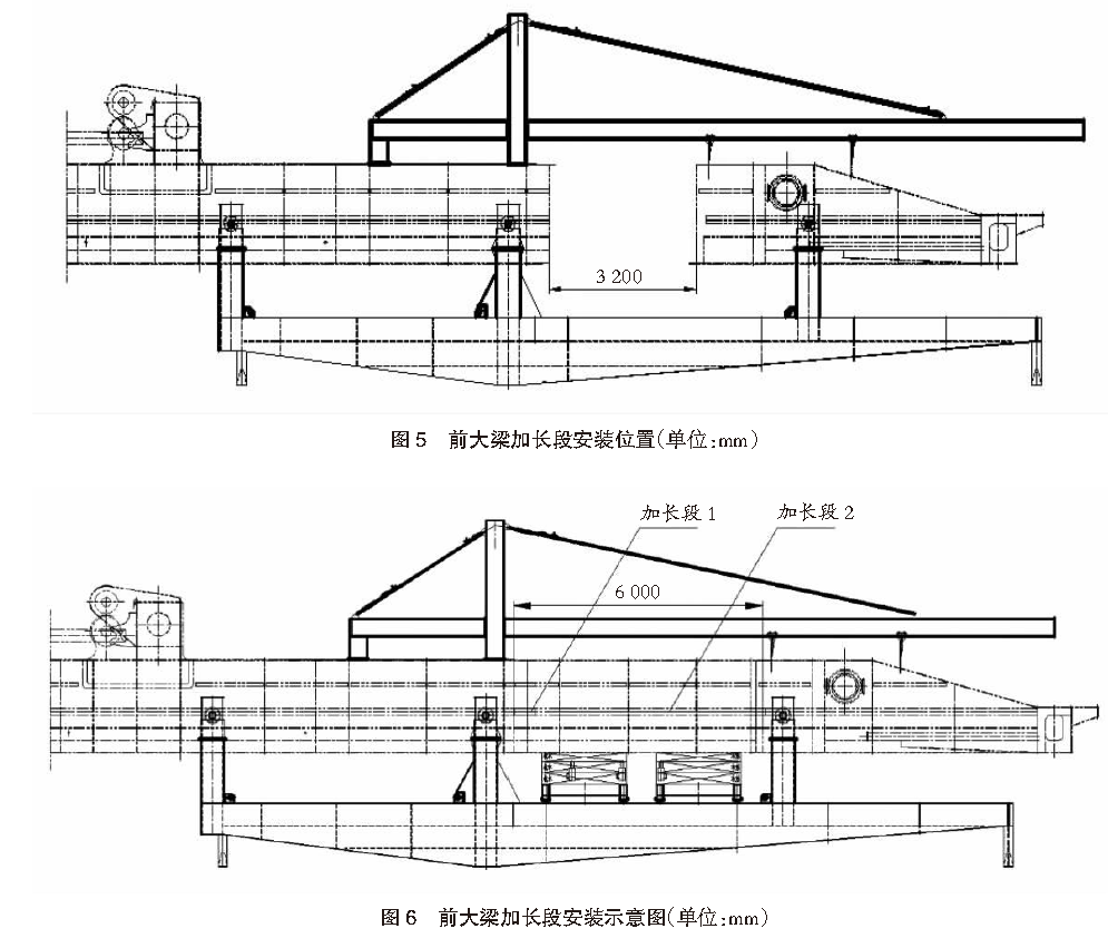
Install accessories such as trolley tracks, track pads, and track pressure plates on the extended section structure, and install back bows near the pulling points of the front row tie rods. Remove the fixed cantilever crane, mobile platform and other tooling equipment, restore the positions of the quayside crane trolley and the quayside crane bracket trolley, and complete the lengthening of the front girder structure.
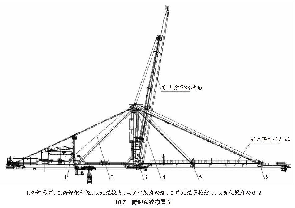
The pitching system mainly consists of a pitching mechanism and a wire rope winding system, which allows the front beam to switch between raising and leveling modes. The pitch mechanism is mainly composed of motor, coupling, brake, reduction box, reel, etc. The wire rope winding system mainly consists of the front beam pulley block, the ladder frame pulley block and the wire rope.
The wire rope passes through multiple sets of pulleys located on the top of the front girder and ladder frame. The rope end is fixed on the pitch drum. The hinge point of the girder is used as the fixed fulcrum, and the pulley set on the front girder is the focus point. The pitch motor drives the drum to rotate, collect or release. Wire rope to raise or level the front beam. The pitch system layout is shown in Figure 7.
The safety factor of the wire rope refers to the ratio of the minimum breaking tension of the wire rope to the load tension of the wire rope. In order to ensure the safe and reliable operation of steel wire ropes, the design specifications of various countries have clear regulations on the safety factors of steel wire ropes. For different work levels, the safety factors of wire ropes are also different. The commonly used working level of the pitch system is M6. According to the requirements of the “Crane Design Code”, the safety factor of the moving wire rope corresponding to M6 must be no less than 5.6. The modified quay crane must also follow this principle.
The tension of the pitching wire rope is related to the center of gravity position of the front girder, the mass of the front girder, the position of the pulley fulcrum, etc. The extended section of the front girder is located on the sea side of the front pulley block, and the position of the pulley fulcrum has not changed. However, the lengthening of the front girder causes the center of gravity of the front girder to move forward and increase the mass, and the corresponding wire rope tension also increases.

In the formula: F is the wire rope tension, t; ηR is the winding system efficiency; G is the equivalent mass of the front girder, t; Lm is the equivalent center of gravity of the front girder, m; n1 is the rear wire rope magnification; n2 is the front wire rope magnification; L1 is The front wire rope moment arm, m; L2 is the rear wire rope moment arm, m.
The extended section structure is located at the cantilever end of the front frame head and does not change the shape of the winding system. It can be seen from equation (1) that the changes in the mass and center of gravity of the front girder after lengthening are the main factors causing changes in the wire rope tension. Taking a conventional double box girder structure and a front girder with a forward extension of 65 m as an example, the changes in wire rope tension before and after the front girder is lengthened by 6 m are analyzed and compared. The schematic diagram of the wire rope winding system is shown in Figure 8. The calculation parameters of the pitching wire rope tension are shown in Table 1.
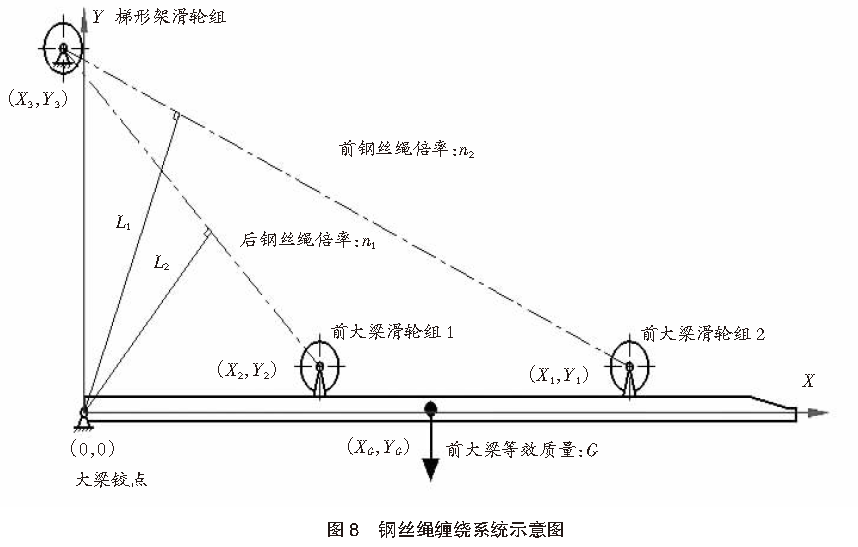

According to the data in Table 1, it is calculated that the tension F of the steel wire rope before lengthening is 15.58 t, and the tension F of the steel wire rope after lengthening is 17.51 t. The change is very obvious.
To determine whether the existing pitching wire rope on the quay crane can continue to be used, you need to check the minimum breaking tension of the wire rope. Use the ratio of the breaking tension to the lengthened wire rope tension to check the safety factor. If the safety factor is less than 5.6, the existing pitching wire rope must be replaced.
The nominal tensile strength of the steel wire rope refers to the stress corresponding to the maximum test tension of the steel wire rope during the tensile test. For steel wire ropes of the same diameter, the greater the nominal tensile strength, the greater the corresponding minimum breaking tension. In order to avoid changes in the pitching drum due to the replacement of the pitching wire rope, the principle of keeping the diameter unchanged when selecting a new wire rope should be followed, and a greater breaking tensile force should be obtained by increasing the nominal tensile strength of the wire rope to meet the specifications. required safety factor.


In the formula: Pe is the rated power, kW; PM is the maximum dynamic power, kW; λ is the motor overload factor, λ takes a common value of 1.6; PS is the maximum static power, kW; Pa is the acceleration power, kW; F is the wire rope tension, t; v is the wire rope speed, m/s; etaR is the winding system efficiency; etaB is the pitching system efficiency; I is the rotational inertia of the pitching mechanism, kg·m2; n is the motor speed, r/min; t is the acceleration time, s.
It can be seen from the above formula that the change in wire rope tension is the main factor causing the change in motor power. Taking the conventional double box girder structure and the front girder with a forward reach of 65 m as an example, based on the wire rope tension calculated previously, the pitch motor power after the front girder is lengthened by 6 m is checked. The maximum static power PS calculation parameters are shown in Table 2. The calculation parameters of acceleration power Pa are shown in Table 3.

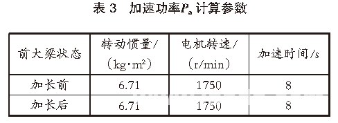
According to the data in Table 2 and Table 3, it can be calculated that the rated power Pe of the extended front pitch motor is 260.43 kW, and the rated power Pe of the extended pitch motor is 290.51 kW. The rated power Pe of the extended pitch motor becomes significantly larger.
The motor overload factor λ is the ratio of the motor’s maximum torque to its rated torque. The commonly used quay crane pitching motor is a three-phase asynchronous motor, and its overload factor is generally 1.6 to 2.2.
With the consent of the motor manufacturer, the motor rated power can be rechecked by increasing the motor overload factor. Raise the motor overload factor λ from 1.6 to 1.8, and recalculate according to the data in Table 2 and Table 3. The rated power Pe of the extended pitch motor is 258.23 kW, which does not exceed the rated power Pe of the extended motor of 260.43 kW. The original motor can continue to be used. .
Structural stiffness refers to the ability of the structure body to resist deformation under the action of external loads. The free end of the front girder will deflect under load. The degree of deflection is an external manifestation of the structural stiffness of the free end.
After the front girder is lengthened by 6 m, the length of the cantilever end of the head is greatly increased, and the degree of stress and downward deflection deformation is also significantly increased. In severe cases, it may cause deformation and cracking of the structure. In order to avoid this extreme situation, a back arch structure can be added near the front tie rod to effectively solve the problem of strength and deformation of the rear cantilever end of the multi-box lengthened front girder. The back arch structure can effectively transfer part of the load to the beam body inside the tie rod, thereby reducing the stress on the free end and the downward deflection of the beam head, and enhancing the structural rigidity. See Figure 9 for the installation location of the back arch structure.

Since the structure of the front girder of the quayside bridge is relatively complex, the structural analysis function in ANSYS finite element analysis software can be used to intuitively simulate the degree of deflection of each position of the front girder structure under different loads.
Taking the front girder of a double box girder structure as an example, a load of 65 t is loaded at the forward reach position, and the structural analysis function in the ANSYS finite element analysis software is used to simulate the downward deflection of the front girder head. The simulation diagram of the downward deflection of the front frame head is shown in Figure 10.
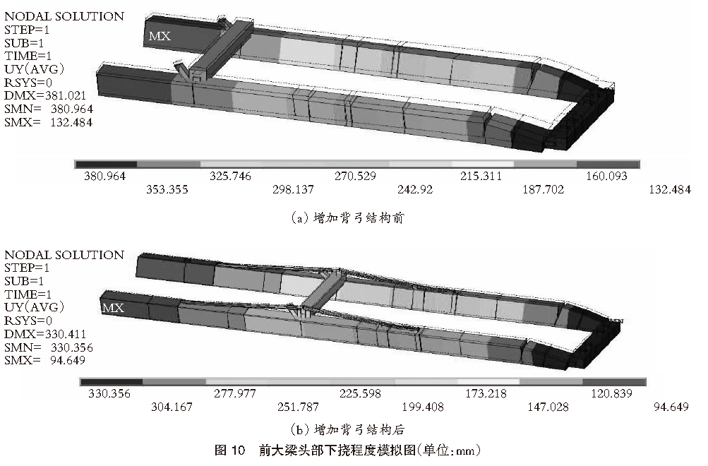
It can be seen from Figure 10 that before the back arch structure is added, the maximum downward deflection value of the front girder head under rated load is 381 mm; after the back arch structure is added, the maximum downward deflection value of the front girder head under rated load is 330 mm. . After adding the back arch structure, the maximum deflection value of the front girder head is significantly reduced, which proves that the back arch structure is helpful in improving the structural stiffness of the front girder.
The forward reach of the quay crane is located at the cantilever end of the front girder, and the structural strength at this location is closely related to the length of the cantilever end. As the length of the cantilever end increases, the structural stress at the forward reach position will also increase significantly. One of the main functions of increasing the back arch structure is to reduce the structural stress at the forward reach position and ensure that the strength of the lengthened front girder meets relevant design specifications.
Taking a conventional double box girder structure and a front girder with a rated load of 65 t as an example, ANSYS finite element analysis software was used to analyze the structural stress at the forward reach position. The structural stress simulation diagram at the forward reach position is shown in Figure 11.
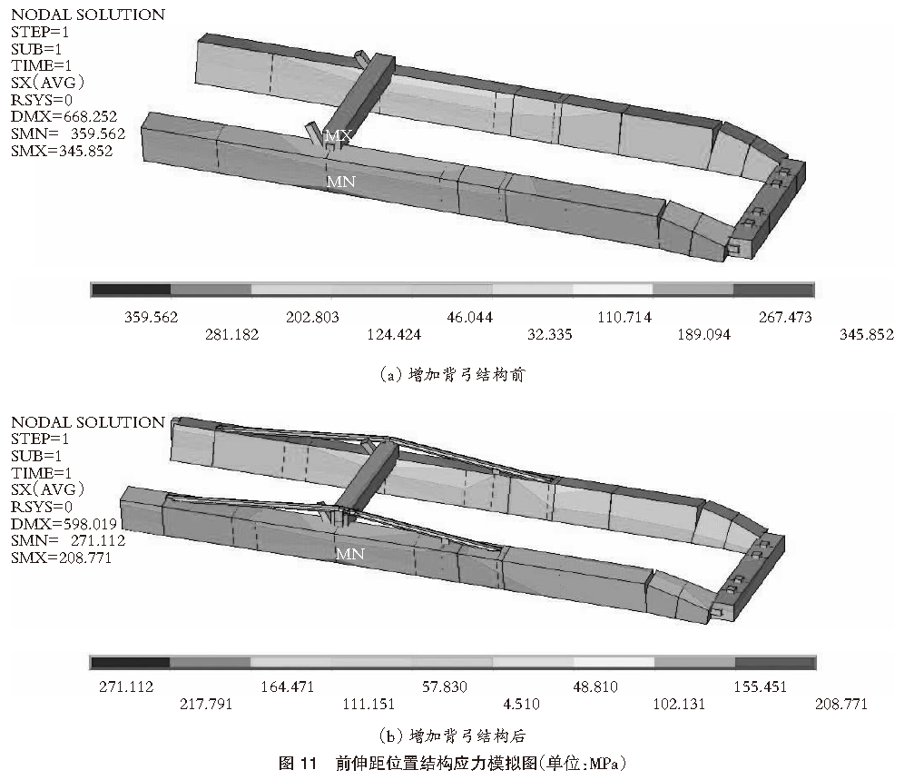
It can be seen from Figure 11 that before adding the back arch structure, the maximum stress value at the forward reach position is 359.56 MPa; after adding the back arch structure, the maximum stress value at the forward reach position is 271.11 MPa. After adding the back arch structure, the maximum stress value at the forward reach position is significantly reduced, which proves that adding the back arch structure can effectively improve the strength of the front girder structure.
The application of the front girder multi-box aerial lengthening technical solution can significantly reduce the construction period and construction costs at the port site. The on-site construction team does not need to lay a large number of temporary tracks on the pier and rent moving equipment to move the quay crane. The construction team only needs to rent an ordinary truck crane to complete the lifting and assembly of the extended core device and the installation of the extended section.
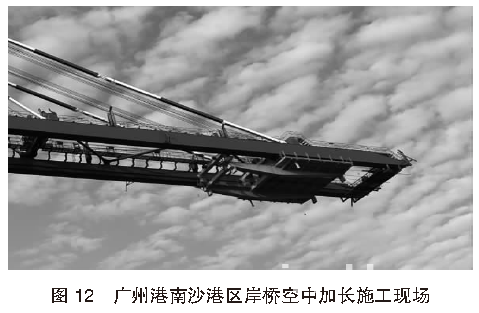
In 2019, the technical solution for the multi-box aerial lengthening of the front girder was applied for the first time on the quayside bridge project in the Nansha Port area of Guangzhou Port. The construction period for the on-site completion of the aerial lengthening of the front girder of the first quayside bridge was only 20 days. If the traditional front girder lengthening scheme is adopted, the construction period of a single quay crane on site will take at least 45 days. At the same time, the construction cost of the front girder multi-box aerial lengthening technical solution is only about 60% of the traditional solution. The construction site of the aerial extension of the quayside bridge in Nansha Port Area of Guangzhou Port is shown in Figure 12.
The lengthening core device is the key to the multi-box aerial lengthening technical solution for the front girder. This device can be used to lengthen the front girder in the air. At the same time, installing a back arch structure near the front tie rod can effectively solve the problem of strength and stiffness of the rear cantilever end of the multi-box lengthened front girder. The front girder multi-box aerial lengthening technical solution has been successfully applied in many ports at home and abroad, such as the Port of Guangzhou in China and the Port of Algeciras in Spain, and has achieved remarkable results in shortening the construction period and reducing construction costs.
Original title: Technical solution for multi-container aerial lengthening of front girder of quayside container crane
作者:李波,黄宾;上海振华重工(集团)股份有限公司
Author: Li Bo, Huang Bin; Shanghai Zhenhua Heavy Industries (Group) Co., Ltd.

