–正文– –Body–
A spline is a mechanical transmission element that is typically used to transmit rotational motion and torque. It consists of a series of evenly spaced key teeth that are arranged along the circumferential direction of the shaft.
1) High torque transmission capacity: The key teeth of the spline can provide a large contact area, so that it can transmit higher torque.
2) Accuracy and reliability: The shape and size accuracy of the key teeth of the spline are high, which can ensure the accuracy and reliability of the transmission.
3) Axially sliding: The spline can slide axially, which makes the spline connection have a certain axial adjustment ability.
4) Easy to assemble and disassemble: The key tooth design of the spline makes assembly and disassembly easier, and it is convenient for maintenance and replacement.
Splines are often used in automobiles, machinery, aerospace and other fields, such as automotive gearboxes, transmission shafts, machine tool spindles, etc., splines may be used to achieve power transmission. According to the different shapes and tooth shapes, splines can be divided into various types such as rectangular splines, involute splines, triangular splines, etc.
When designing and manufacturing mechanical transmissions, involute splines are a very important part. It can achieve high-precision transmission, and has the characteristics of wear resistance and high strength. In this article, we’ll cover the design, modeling, and drafting process of involute splines.
There are many standards for splines, and the most commonly used ones in China are GBT3478 and German standard DIN5480/5482. Here we take the 30° round tooth root involute spline in GB/T3478 with modulus of 3 and 27 teeth as an example to describe the size calculation and modeling process of the spline. The public account “Mechanical Engineering Wencui”, the engineer’s gas station!
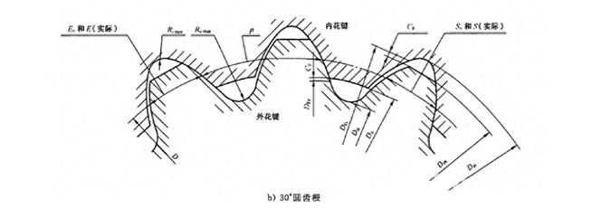
图 1-1 30°圆弧齿根渐开线花键齿形 Figure 1-1 Involute spline tooth shape of a 30° arc tooth root
The minimum value of actual tooth thickness: Smin=S-(T+λ)=S-0.139
Spline base circle diameter: db=d*cos(α)=83.1384
3.1. Enter the above calculation process into the UG expression, as shown in the following figure:
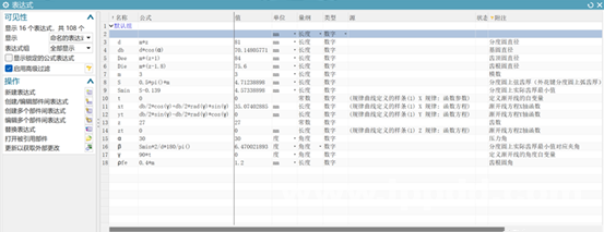
图 3-1 外花键参数化建模表达式 Figure 3-1 Parametric modeling expression for external splines
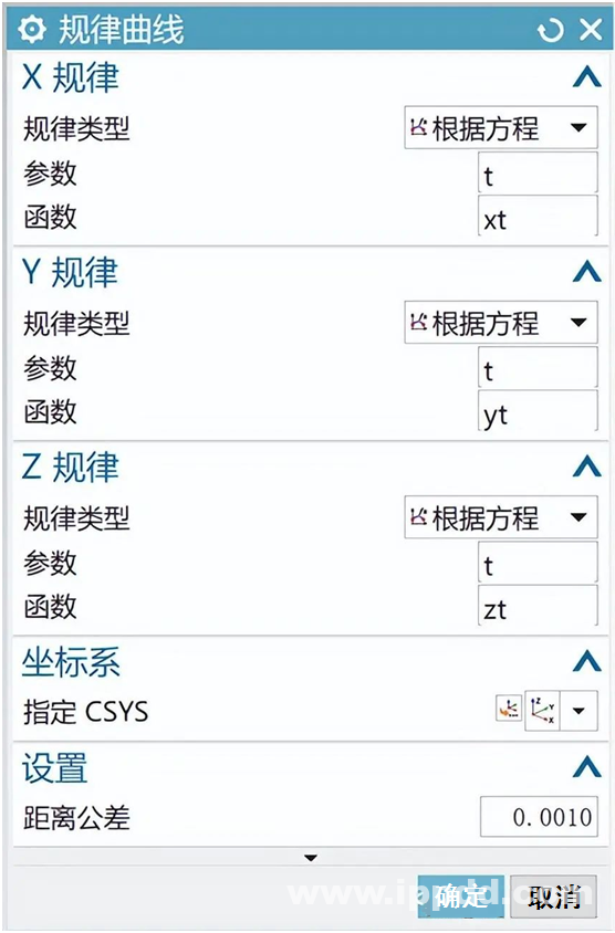
图 3-2 创建渐开线曲线 Figure 3-2 Creating an Involute Curve
This includes the tooth root circle, the indexing circle, and the tooth top circle, where the arc tooth thickness on the indexing circle needs to be constrained to be equal to Smin
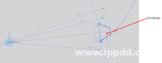
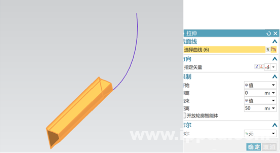
图 3-4 拉伸创建单个花键齿 Figure 3-4 Extrudes to create a single spline tooth
3.4.阵列创建其他花键齿 3.4. The pattern creates additional spline teeth
数量选择“公式”→“Z(花键齿数)” Quantity selection “Formula” → “Z (number of spline teeth)”
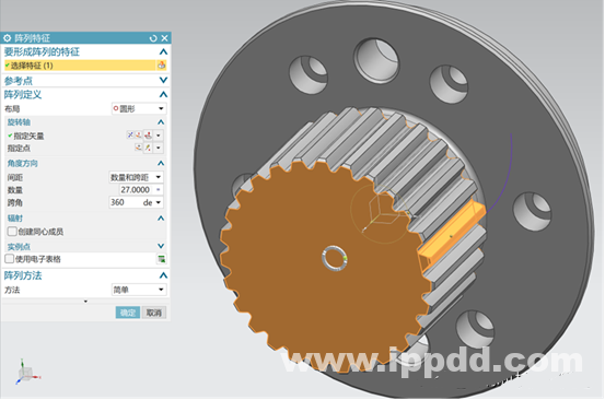
图 3-5 阵列剩余花键齿 Figure 3-5 Remaining spline teeth in the array
3.5.以花键齿根圆为外径,创建拉伸创建一个圆柱体
3.5. Create an extrusion to create a cylinder with the spline root circle as the outer diameter
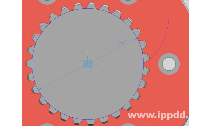
图 3-6 创建外花键内部圆柱体 Figure 3-6 Creating an Outer Splined Inner Cylinder
3.6.将轮齿与圆柱体合并为一个体 3.6. Merge the teeth with the cylinder into one body
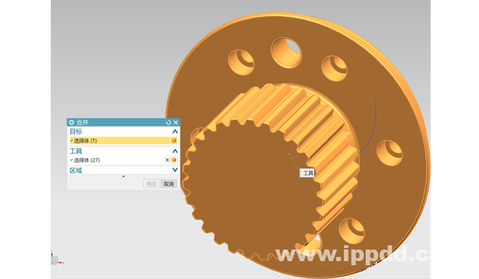
图 3-7 合并花键齿与圆柱体 Figure 3-7 Merging a spline tooth with a cylinder
3.7.创建其他相关结构 3.7. Create other related structures
最终完成花键如下图所示 The final finished spline is shown in the figure below
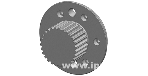
图 3-8 外花键最终模型 Figure 3-8 Final model of external splines
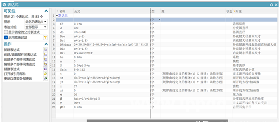
图 4-1 内花键参数化建模表达式 Figure 4-1 Parametric modeling expression for internal splines
最后模型如下图所示: The final model is shown in the following figure:
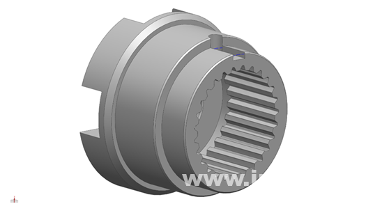
图 4-2 内花键最终模型 Figure 4-2 Final model of internal splines
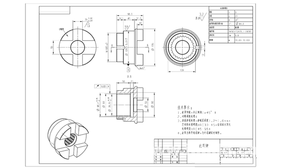
5.花键工程制图 5. Spline engineering drawing
内外花键的工程制图如下,供参考: The engineering drawings of internal and external splines are as follows for reference:
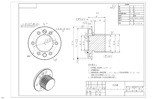
图 5-1 外花键工程图纸 Figure 5-1 Drawing of an external spline
END
声明:部分内容来源于网络,仅供学习、交流。版权归原作者所有。如有不妥,请联系删除。
Disclaimer: Part of the content comes from the Internet, only for learning and communication. The copyright belongs to the original author. If there is anything wrong, please contact us to delete it.
